Progress Bars
Update to fix overlapping Progress Bars:
Download and extract to CAN Create installation folder overwriting .exe and content folders.
Progress Bars are a new feature of CAN Create. Download the attached file which contains an example design (ProgressTest.ccs). Make sure to import the image assets into your Image Library by going to Tools->Open Image Library and selecting Import Image Pack.
After opening the file you will see an example GUI like this:
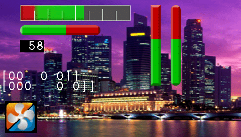
After opening the file in CAN Create be sure to compile the C script before starting the simulator.
There are a variety of different bars and styles shown in this example. Both Horizontal and Vertical bars are possible. The object is added to CAN Create from the Display menu of the object selector.
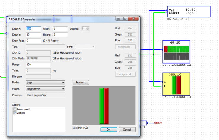
Once added you can double click to set the properties. If using a vertical bar the full and empty graphics should be placed side by side in a single .png. The full graphic will be on the left side and the empty graphic on the right. If the vertical flag is not checked under the object options it will not display correctly. The horizontal bar image is rotated 90 degrees so that the full graphic is on top and the empty graphic on the bottom. The software will automatically divide the image by half in the y or x axis depending on the option selected.
It is important to set the range property to the expected range of the input. The input will be divided into the range and the resulting fraction will determine what percentage of the full/empty graphic to interpolate between. Be sure to scale and offset the input so that it does not exceed the full scale range or go below 0 as the interpolation will not work correctly.
Transparent regions can be used so that the background would be visible for the empty portion. Be aware that using transparent regions will result in a slight delay updating the graphic on the screen.
Multiple progress objects can be overlaid on top of each other provided the enable pins are controlled in a manner that prevents both being active at the same time. The preferred method for implementing this would be the use of the Delay cycle object with an AND gate:
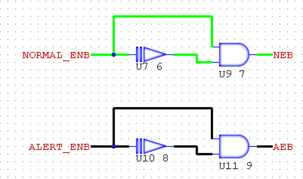
NORMAL_ENB and ALERT_ENB in the above example are derived from a threshold trigger. If the value going to the Progress object is greater than or equal to 80 the ALERT_ENB will be set, whereas below 80 the NORMAL_ENB will be set. The Delay cycle object will insure that the output NEB or AEB which is tied directly to the ‘E’ pin of the Progress object will be false prior to the opposite one becoming true. By using this technique the gauge could be made to flash or change color depending on a defined threshold which can improve operator awareness of critical information.